Ground & Formation Models
Excavation, embankment, platform, formation, subgrade, slopes, boundaries and breaklines.
UK MACHINE CONTROL • LANDXML • 3D CONSTRUCTION DATA
Turn approved drawings and survey information into clear, reviewed digital construction data for roads, earthworks, excavation, formation and compatible machine-control workflows.
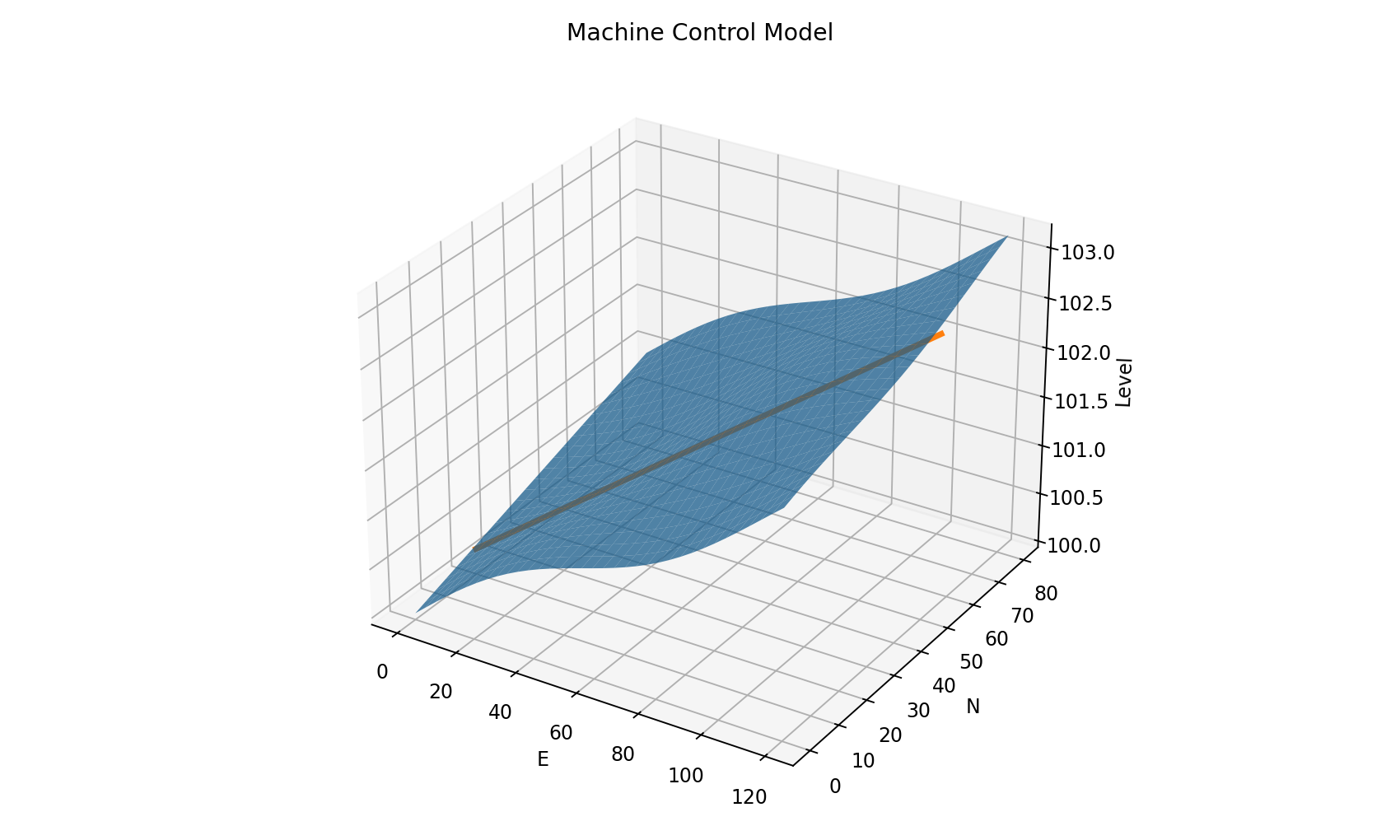
WHAT WE PREPARE
Excavation, embankment, platform, formation, subgrade, slopes, boundaries and breaklines.
Centreline, channels, kerbs, tie-ins, crossfall, junction geometry and road formation where supported by the source design.
Reduced levels, pits, trenches and construction surfaces prepared to an agreed design basis.
3D routes and trench information can be coordinated with the model where the required levels and geometry are supplied.
Coordinates, points, lines, design-versus-survey information and model checks for agreed workflows.
Tell us the target software, machine-control environment and required deliverable before export.
WORKFLOW
Drawings, survey files, sections, coordinates and project brief.
Units, coordinate system, datum, levels, gradients and missing information.
Build the agreed 3D geometry, breaklines and/or TIN surface.
Review continuity, boundaries, tie-ins, levels and export structure.
Issue agreed DXF, XML/LandXML, TIN/DTM, schedules, views or report.
SYNTHETIC DEMONSTRATION
This example uses synthetic local coordinates and levels. It demonstrates the type of information and deliverables that can be prepared without presenting fictional data as a real construction design.
RELATED EXAMPLES
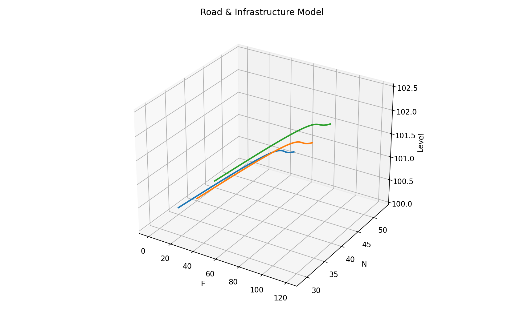
Illustrative centreline, channel and formation geometry.
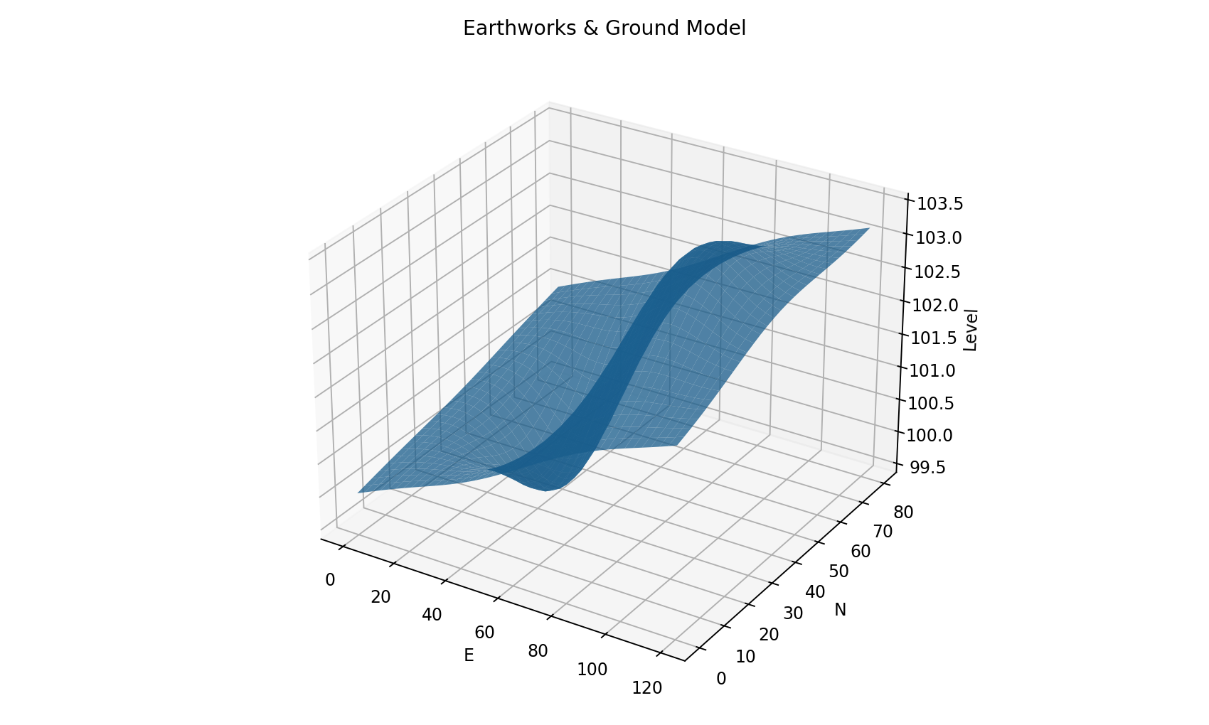
Illustrative excavation, fill and terrain surface.

See a wider multi-discipline example with interactive model, QA views and capability report.
VIEW CASE STUDY →DEMO DOWNLOADS
DELIVERABLES
3D polylines, breaklines, boundaries, points and structured layers.
Supported TIN surfaces and model information for compatible downstream workflows.
Formation, excavation, earthworks or design surfaces prepared to the agreed scope.
Coordinates, levels and schedules where required.
Model views, summaries, checks and supporting documentation.
Confirm the machine/control system, software version and expected file structure before delivery.
FAQ
No. A usable model depends on the quality and completeness of the source design. Coordinates, levels, geometry, sections and the intended construction layer must be established rather than guessed.
LandXML/XML can be prepared where the model and target workflow support it. The required surface, alignment and downstream system should be agreed before export.
We can prepare construction model information for compatible machine-control workflows. Final compatibility and field use must be confirmed against the specific system, project requirements and approved design.
Typical inputs include PDF, DWG/DXF, XML/LandXML, survey CSV/TXT, coordinates, sections and written scope information.
Missing or unclear design information is identified during review. Engineering levels or design intent are not silently invented.
START A PROJECT
Tell us what you have, what you need and the intended machine-control or survey workflow. We can then define the model scope and deliverables.
For confidential drawings, agree a secure transfer method before sending project files.